Project 1: Booting Your Own Operating System
In this project, you will write the code that takes a Raspberry Pi from the moment it powers on to the point where it can run a sequence of programs, one after another. By the end, you will have built a tiny operating system that performs batch processing: it loads a program into memory, runs it to completion, and then loads and runs the next one—the way the very first operating systems worked in the 1950s and 60s.
You will start with nothing. There is no operating system underneath you, no C standard library, no printf, just you and the hardware. The hardware powers on, places your code in memory, and starts executing it. Everything else is up to you.
This is called “baremetal” programming and is a different kind of programming from what you did in CS 300 or other prior systems courses. There, the operating system—and, specifically, the kernel—gave your program a stack, loaded it into memory, connected stdout to your terminal, and isolated your bugs from everyone else’s. Here, there are no other programs are running, and in the first step, there isn’t even an OS or a kernel.
Initially, your OS will do very little. Over the course of CS 1670/1690, you will build out from this primitive OS to something that approaches the feature set of a modern operating system.
Learning objectives
After completing this project, you will be able to:
- Explain why a computer needs a boot process and what it must accomplish. You will understand that the hardware determines the machine’s physical memory layout—including where devices appear in memory for memory-mapped I/O (MMIO)—and that you must consult hardware manuals to discover this layout. You will also know what the essential steps in the bootup process are.
- Explain why hardware needs device drivers to do anything useful, and write one: a driver for a device called a “serial console” that lets you print output.
- Explain how an operating system loads and runs a user program. You will see that a program’s executable (a compact file of machine code and data) is a different thing from a running program (a set of memory segments), that the OS must load the executable into memory before it can run, and that the OS decides where in memory to put it.
- Explain the role of the operating system as the layer that abstracts the hardware away from programs and as the mediator that decides which program runs.
The Raspberry Pi’s CPU uses the ARM64 architecture, which is a different hardware architecture from the x86-64 you saw in CS 300, or the architectures you may have seen in other Brown systems courses (e.g., CS 1650 uses x86-32, CS 1952-Y uses RISC-V). So, as a secondary learning objective, you will also become familiar with the ARM64 architecture, its registers, its instructions, and its conventions, and learn to read and write basic ARM64 assembly. To help you adapt your skills to ARM64, we provide a quick reference doc to help you get started – we’ll refer to this in throughout the handout.
CS 1670 vs. 1690/2670
All projects in the course are shared between CS 1670 (the basic “Operating Systems” course) and the lab, CS 1690/2670. However, students in CS 1690/2670 will work with real hardware and complete extra tasks that allow them to go deeper on the assignments.
Hardware Needs
If you are taking CS 1690/2670, you will work with a real Raspberry Pi 3B+. This means that your code for this project will need to work on the real hardware.
We will provide you with the Raspberry Pi as well as some peripherals (power supply, microSD card, and a TTL-to-USB serial cable) at the end of shopping period. Please see our hardware ordering and information page for more information.
For this project, you will access a physical Raspberry Pi remotely via the grading server or come to instructor office hours to run your code on the hardware.
Note that real hardware often unearths bugs that do not appear in QEMU. If you are taking CS 1690/2670, you should test your code on the real hardware as soon as possible to avoid surprises later in the project. See the extra handin requirements for CS 1690/2670 and familiarize yourself with them early.
In this project, you will mostly work in a machine emulator (QEMU) that emulates a Raspberry Pi. At the end of the project, students in 1690 will run their code on real hardware.
Here is the summary of the quests you must complete for this project, based on which course you’re enrolled in:
| CS 1670 | CS 1690/2670 |
|---|---|
| Complete quests 1–3 in QEMU (emulated Raspberry Pi). | Complete quests 1–3 in QEMU (emulated Raspberry Pi) |
| Run your OS on real hardware (Raspberry Pi). |
Roadmap
The project has three tasks (“quests”), which build on each other:
| Task | What you build | What you learn |
|---|---|---|
| 1. Boot | Assembly bootup code (kernel/boot.S) that starts a bare-metal program that estimates π. | The boot process: choosing a CPU, the stack, zeroing globals, jumping into code. |
| 2. Output | A driver for the ARM PL011 Universal Asynchronous Receiver/Transmitter (UART) and a printf implementation, used to print π. | Memory-mapped I/O and device drivers. |
| 3. Run programs | A minimal kernel (kernel/kernel.c) that loads ELF executables and runs several programs in sequence, sharing printf across them. | Executables vs. processes, ELF loading, the OS as abstraction and mediator. |
The next two sections describe how to get started with the assignment code. After you get set up, read the Background section next – it gives you the conceptual and ARM64 foundation you need for all three tasks. Then, work through the tasks in order.
Assignment Installation
If you have completed Project 0, you will already have created a private GitHub repository for your project work under the csci1670 organization.
⚠️ If you have not completed Project 0, you should do it now. You will need software installed as part of Project 0 to complete this project.
While CS 1670/1690 projects have little stencil code, we do provide you with a repository structure and a build system to get started. You will need to pull this into your projects repository, as follows:
Open a terminal in your container environment and
cdinto the directory you setup as your project repo in Project 0 (e.g.,cd projects).Run the following command to pull the latest code from the
handoutremote:git pull handout mainIf this reports an error, run:
git remote add handout git@github.com:csci1670/cs1670-f26-projects.gitfollowed by:
git pull
git pull handout main
This will merge our provided files with your repository.
Working on projects with VS Code
If you use VS Code (or one of its derivatives), there are two important parts of your IDE set up to check as you get started developing your OS:
How to open this repository
First, we need to make sure VS Code knows how to compile the code. This will make sure you can receive warnings on syntax errors, and can use Ctrl+Click (Windows) or Cmd+Click (macOS) to jump to where functions are defined. To do this:
If you have not done so already, open VS Code. If you use the container version, attach it to your container.
In the VS Code menus, go to File > Open Folder and navigate to your
projectsfolder. Be sure to open this folder directly (don’t use your dev environment folder, yourcs1670folder, or your desktop).Follow the instructions from project 0 to test your VS Code: native macOS version, Container version. If your initial setup worked, everything should be fine, but it’s important to check here since you’ll be using this repository all semester!
Disabling VS Code AI features (recommended)
CS 1670 has an open AI policy, and we will encourage you to use AI tools on many assignment tasks. However, we recommend disabling your IDE’s automatic AI suggestions as you work on your code, for two reasons:
- There will be tasks where you should write the code yourself in order to understand the concept. For these tasks, an automatic AI suggestion may circumvent your learning by giving you an answer before you’ve had the chance to work it out on your own. We don’t want you to miss out on learning the concepts that are most important, so that you have these skills for later projects and outside the course.
- Writing operating system code often differs from normal conventions in C programming, and AI can be wrong if it assumes these conventions hold. For example, our project has no system header files (e.g.,
stdio.h,stdlib.h), because these are part of your operating system. Similarly, AI often suggests x86-64 assembly instructions, even though our OS is written for the ARM64 architecture. Therefore, automatic AI suggestions from cheap models are likely to suggest incorrect code, especially as you’re getting started. As you work on the projects, we will provide guidance on how to prompt the AI to generate code that will work for us—so this is a skill you will learn!
To disable VS Code’s automatic AI features, do the following (example in the figure below):
- Click on the gear menu in the bottom-left corner and select Settings
- Search for “disable AI features” and check the first result:

For more details on AI use in CS 1670, please see our AI policy and the guidance at the end of each task in our handouts.
Code Structure
In this course, you will build your own operating system from the ground up. This means that you own every line of code, make all the key design decisions, and will really understand how key pieces of an OS work because you’ll design and implement them yourself.
Unlike other courses that provide you with stencil code in which you fill in specific functionality, in CS 1670 you write all significant code yourself. However, most operating systems’ code bases follow certain best practices and conventions, and we provide you—in this project and subsequent ones—with a skeleton of empty files that we recommend you structure your code into. We also provide a build system, so that you don’t have to wrangle the details of composing a Makefile that works with QEMU, GDB, and the somewhat arcane incantations required to build low-level OS code.
After you clone our stencil, you’ll find that it contains a build system and a skeleton layout of .c, .h, and .S files — most of them empty. You will fill these in.
.
├── Makefile
├── docs/                 ← Folder for screenshots, notes, memory layout diagrams, etc.
├── kernel/
│   ├── boot.S            ← Task 1: bootup assembly
│   ├── drivers/
│   │   ├── uart.c, uart.h   ← Task 2: the UART driver
│   │   └── gpio.h           ← Task 2: GPIO register definitions
│   ├── kernel.c          ← Task 3: the kernel's main loop
│   ├── elf.c, elf.h      ← Task 3: ELF format definitions + parsing
│   ├── init.c            ← Task 3: load + run one executable
│   ├── linker.ld         ← linker script that defines memory layout for kernel
│   ├── memlayout.h       ← physical memory layout constants
│   ├── mm.S, mm.h        ← memory-related helpers
│   ├── utils.c, utils.h  ← helper functions/macros, including for MMIO
│   └── ...
└── user/
    ├── pi.c              ← Task 3: the π-estimating program
    ├── u_klib.h          ← Task 3: the user-side library (access to printf)
    └── ...               ← more user programs for Task 3
Building and running
The build system uses make. The most important targets are:
$ make qemu        # build the image and run it in QEMU
$ make qemu-gdb    # same, but pause and wait for a debugger to attach
$ make clean       # remove build artifacts
make qemu boots your code in an emulated Raspberry Pi 3B+. The Pi’s serial console (the device you’ll write a driver for in Task 2) is connected to your terminal, so anything your code prints appears there. In a real early-days computer, this console would have been a typewriter, just like you saw in class.
Note: QEMU captures your terminal. This means that key combinations like Ctrl-c get sent to your OS inside QEMU, rather than to your terminal application. This can make it a rather difficult to quit QEMU when your OS hangs (i.e., switch off the emulated machine).
To quit QEMU, type Ctrl-a then x (press and release Ctrl-a, then press x). To send a command to QEMU’s internal “monitor” instead of the emulated machine, use Ctrl-a then c. You can enter commands like quit or help into the monitor.
If you ever lose track of your QEMU or the terminal that contains it, running make kill in a fresh terminal will get rid of any lingering QEMU instances. Doing this is important, because QEMU can drain your laptop’s battery very fast because it runs four simulated CPUs at full speed.
Debugging bare-metal code is hard. There is no gdb running inside the machine and, until Task 2, no way to print anything. Instead you attach a debugger from outside the emulator:
# Terminal 1:
$ make qemu-gdb        # starts QEMU, paused, listening for gdb on port 1234

# Terminal 2:
$ cd YOUR_PROJECT_DIRECTORY   # important to run `gdb` from your project directory
$ gdb                  # (or `gdb-multiarch` on Linux/WSL)
Our stencil code ships a .gdbinit that connects to QEMU automatically and loads your kernel’s symbols. This is why running gdb inside your project directory is important: by doing so, you pick up the GDB configuration we provide. From there you can set breakpoints, step through instructions, and inspect registers. See Appendix C for a cheat sheet.
Background
What happens when a computer turns on?
When you run a program on your computer, an enormous amount has already happened before your main function runs. The OS loaded your executable from disk, gave it a fresh stack, zeroed its global variables, and arranged for printf to reach your terminal. None of that exists on bare metal.
Here is what actually happens on a Raspberry Pi 3 when it powers on:
- A small first-stage bootloader baked into the chip reads firmware and your kernel program (often called an “image”) from the SD card. This firmware is software, but you cannot change it (making it “firm”). Firmware doesn’t run on the actual ARM processor: instead, due to architectural quirks on the Raspberry Pi, it runs on the VideoCore Graphics Processing Unit (GPU).1
- The firmware copies your kernel image into RAM at a fixed physical address (on Raspberry Pis, this is
0x8'0000) and then starts the CPU cores to begin executing at the first byte of your image. - All four CPU cores (i.e., processors) start running the same code at that same address, at essentially the same time.
At this point there are no abstractions whatsoever. There is just a set of processors, some physical RAM, a fixed memory map, and your instructions. The first thing your code runs is whatever you placed at the entry point. This is why you will write your code for Task 1 in assembly: there is not yet a stack, so you cannot yet run C. This is one of the few places where programmers still hand-write assembly code today.
Why does having a stack matter?
Compiled C code assumes a working stack pointer. It pushes return addresses, spills local variables, and passes arguments using the stack. If you call a C function before setting up the stack pointer, the very first thing that function does will corrupt memory or crash. So, a few instructions of assembly must run first to establish the conditions C needs.
The OS as abstraction and as mediator
Step back and notice the two big jobs an OS does, both of which you will implement in simple forms in this project:
- Abstraction. A user’s program should not have to know that the serial console/UART device lives at physical address
0x3F20'1000, or how to configure it, or how a program’s memory segments are laid out. The OS hides all of that behind clean interfaces (e.g., aprintffunction the program can just call). - Mediation. Hardware resources on the computer are shared between programs, but such sharing must be orchestrated. For example, only one program can use a CPU at a time, so something must decide which program runs and when. In this project, your OS is the mediator: it picks the next program, loads it, runs it to completion, and then picks another.
Keep these two roles in mind; in the first part of the project, there is no OS, and neither of them exist. In the second and final part of the project, you will write code to make your OS perform these roles.
Quest 1: Boot into a bare-metal program
Files: kernel/boot.S, kernel/pi.c (and you’ll read kernel/memlayout.h, kernel/mm.S, kernel/linker.ld).
Overview
You will write the assembly code that runs at the very first instant the machine starts running, prepare the machine so that C code can run, and then jump into a C program—pi.c—that estimates π and spins forever. There is no kernel and no OS yet: boot.S and pi.c are linked together into one program that is the only program to run on the machine. This is the kernel “image” we referred to earlier, although there is no kernel yet: this task is purely about getting from power-on to running C code.
Why are we doing this?
Every operating system, no matter how large, begins with a few dozen instructions exactly like these. Before any C code can run, something must establish the conditions C depends on. Doing it yourself, once, demystifies the idea of “booting”, even though our example is a rather simple boot process. It also gives you a first, gentle taste of ARM64 assembly with a very small amount of code.
Notes on the ARM64 CPU achitecture
The Raspberry Pi’s CPU is based on a processor architecture made by a company called Arm. This 64-bit architecture has many names: it’s often referred to as “ARM64”, but also sometimes called “AArch64”. (Very pedantically, AArch64 is the 64-bit execution state of an architecture called “ARM”.) Practically all modern smartphones and mobile devices use ARM64 processors, as do “Apple Silicon” MacBook laptops. This is largely because ARM processors have significantly lower power consumption than x86-64 ones—something that matters when your device runs on a battery, like a phone or laptop does.
In written materials about the architecture such as ARM’s own manuals, you may also find references to ARMv8, ARMv8-A, and ARMv9. These refer to revisions of ARM’s processor architecture: ARMv7 and earlier were 32-bit designs (AArch32/ARM32), while ARMv8 and ARMv9 are 64-bit designs (and thus part of AArch64/ARM64). The Raspberry Pi 3B+ uses the ARMv8 architecture; some newer RPis use ARMv9 processors, which add some extra instructions and features.
For the purpose of this course, you can think of “ARMv8”, “AArch64”, and “ARM64” as synonymous; however, note that only the latter two (“AArch64” and “ARM64”) are true synonyms.
A 5-minute ARM64 primer (if you know x86-64)
You know the x86-64 architecture from CS 300/1310 and may remember some of its assembly instructions. ARM64 is another processor architecture with a different assembly language. Here are the differences that matter for this project; a fuller reference is in Appendix A.
- Lots of registers. ARM64 has 31 general-purpose registers, named
x0throughx30when used as 64-bit registers, orw0–w30when used as their 32-bit halves. (Compare x86-64, which only has 16 general-purpose registers.) Reads/writes to awregister zero the upper 32 bits of the correspondingxregister, just like the%eXXfamily of 32-bit registers does to the%rXXfamily 64-bit registers in x86-64. - The stack pointer is special. In ARM64, there is a dedicated
spregister; it is not one ofx0–x30. (In x86-64,%rspis one of the 16 general-purpose registers.) - A zero register. The name
xzr/wzrreads as zero and discards writes. This is handy for clearing memory, but has no equivalent in x86-64. - Load/store architecture. This is the biggest conceptual shift. Like in x86-64, ARM instructions that do arithmetic operate on registers. But unlike x86-64, which uses the
movfamily of data movement instructions to move data to/from registers, ARM64 requires you use explicitldr(load) andstr(store) instructions. In addition, there is no equivalent toadd (%reg), %regon x86-64, where(%reg)refers to the memory at the address stored in%reg. You always have to move data into a register first. - Fixed-width instructions. Every ARM64 instruction is exactly 4 bytes, while x86-64 instructions vary in length.
- The return address lives in a register. A “branch with link” (
bl) puts the return address into the link registerx30(also calledlr) instead of pushing it on the stack.retjumps to whatever is inx30. By contrast, x86’scallpushes the return address onto the stack. - Calling convention. The first eight integer/pointer arguments go in
x0–x7; return values come back inx0(cf.%raxin x86-64). Unlike in x86-64, where arguments are stored on the stack in addition to being passed in registers (at least without compiler optimizations), ARM64 requires arguments 1–6 to always be passed in registers only. So, a C functionvoid f(unsigned long a)reads its argument fromx0. - System registers. CPU control and status live in special system registers (also called “machine-specific registers”). You read and write these with the special
mrs(read) andmsr(write) instructions, not ordinarymovs.
That is enough to read and write the handful of instructions Quest 1 needs. Refer to Appendix A whenever you meet an unfamiliar one.
What you need to do
Here’s the plan for getting started. You’ll start by creating a helpful diagram of your operating system’s memory layout and will then write ARM64 assembly code for booting the machine in kernel/boot.S.
Memory Layout Diagram
One of the important roles of an OS kernel is to chop up the machine’s physical memory into different regions that will be used for different purposes. The kernel is typically the only piece of software in the computer (other than the bootloader) that deals with physical memory directly. But it has many decisions to make, and in this project alone, you’ll define four different key memory locations for your OS, with more to come in the future.
To keep track of this, OS developers use memory layout diagrams that visualize what physical address ranges are allocated for different purposes. Some allocations are dictated by the hardware (e.g., where memory used to do memory-mapped I/O with devices is), but others are yours to choose. You will also create and maintain such a diagram across your assignments in this course.
Here’s the initial physical memory layout of a Raspberry Pi 3B when it turns on:
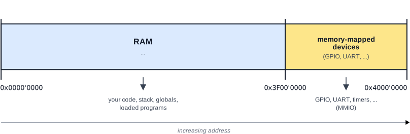
This picture has nothing in it except for the delineation between addresses that correspond to RAM and those mapped to devices (for memory-mapped I/O; more on that later). You’ll fill in parts of this picture throughout the assignment.
Task: Create a memory layout diagram for yourself. You can draw it on an iPad or on your computer, or even on paper. You’ll keep adding to it; for now, it should just be a copy of the above diagram.
When you submit this project, you’ll hand in a PDF file in docs/memlayout-physical.pdf that documents your memory layout.
🤖 AI use/coding: NOT allowed. Why? We want you to develop a mental image of your OS’s memory layout.
For context, see the principles around AI use in CS 1670.
Bootup Assembly Code
The file currently contains two #include statements to include headers that we will use in the future, and two lines. The first of these lines says that the assembly code should be part of the .text.boot segment of memory and .globl _start declares a global label.
#include "memlayout.h"

    .section ".text.boot"
    .globl _start
The entry point to a kernel is conventionally at a label called _start, placed first in the kernel “image” so it sits right at the address where the kernel gets loaded in memory. Your code should therefore start with a line that defines the start label, _start:. Any code you write after the _start: line in your file will run right at bootup.
The code at this label must do four things, in order:
- Park all but one CPU core. All four CPUs on the Raspberry Pi begin executing your code simultaneously, but bootup must run on exactly one. Read the current core’s identity from the
MPIDR_EL1system register into a general-purpose register. The lowest eight bits in the register identify the core number; consider how you might extract these lowest eight bits only! On the one boot core (core 0), continue; on every other core, branch to a label that spins forever (an infinite branch-to-self). This loop is why we say bootup happens on a single CPU while the others are paused. - Zero the global variable segment (
.bss). C assumes that uninitialized global and static variables start at zero. On bare metal, nothing has done this for you. The linker script (linker.ld) defines symbols marking the start and end of the.bssregion. You can access the addresses that these symbols correspond to via theadrinstruction: for example,adr x0, bss_beginputs the start address of.bsssegment into thex0register. Compute the.bsssegment’s length and clear it. We provide a helper,memzero, inkernel/mm.Sthat you can call for this purpose. Read it, as it is a good, short example of ARM64 assembly. - Set up the stack. Point the stack pointer
spat the top of the region reserved for the kernel stack. We provide a constant for this inkernel/memlayout.h(INITIAL_KERNEL_STACK). You get to choose the location, since it is arbitrary and not defined by the hardware. A good choice would be an address far away from the kernel (which is at0x8'0000) and which doesn’t overlap with any other memory regions you’re using (e.g., device registers). Without setting this constant and initializingsp, the first C function call will misbehave. - Jump into C. Use ARM64’s “branch with link” assembly instruction to jump to
pi_main, the C entry point of the π program (kernel/pi.c), to start running it.
Why can boot.S reference INITIAL_KERNEL_STACK, a macro defined in a C header memlayout.h?
A more specific version of the question is how an assembly script #includes a C code file like memlayout.h, especially since we above explained that you can’t use C because we don’t have a stack yet!
Answer: memlayout.h only defines constants; it doesn’t actually contain any C code in the conventional sense (e.g., it creates no variables or functions). Instead, the #define lines in the file define constants that the compiler’s preprocessor will insert into the assembly file before the assembler sees it.
In the build system (Makefile), the .S files are processed like this: Run the C preprocessor (cpp) to expand #include, #define, macros, etc., then feed the pure assembly to the assembler (as).
Since memlayout.h uses #define INITIAL_KERNEL_STACK SOME_VALUE, the preprocessor replaces every occurrence of INITIAL_KERNEL_STACK before the assembler ever sees it. So the assembler just sees ldr x0, =SOME_VALUE (with SOME_VALUE replaced with an actual integer).
Task: Write the bootup assembly code in kernel/boot.S. Update your memory layout diagram to indicate the memory region used for the kernel and the location of the initial kernel stack.
🤖 AI coding: NOT allowed. Why? We want you to understand what happens when you boot a machine by writing the code by hand yourself. We encourage you to ask AI questions about ARM64 assembly, however; it produces very readable explanations that are much more accessible than ARM’s documentation.
For context, see the principles around AI use in CS 1670.
Hints
- Read
kernel/mm.Sand the linker script first.memzeroshows you the ARM64 idioms you need (post-indexed stores,subs/conditional branch). The linker script (linker.ld) shows you the.bssstart/end symbols and confirms that your boot section is placed first, at the load address0x8'0000. - Keep
boot.Stiny. If it is more than ~15 instructions, you are probably doing too much. Save real work for C. - Don’t try to get fancy and remember that the whole machine is yours. You can just use any memory address however you want.
- Make step-by-step progress and use GDB to check that your code runs, e.g., by single-stepping it or setting breakpoints on the instructions you added.
- Our build system will link
pi.cprogram with your bootup assembly: they’re all part of the same machine code and code segment. Hence, you can simply jump to a function in the C program (i.e.,pi_mainin this case). - To use constants defined elsewhere in the code in assembly, use the
=CONSTANT_NAMEsyntax. For example,ldr x0, =INITIAL_KERNEL_STACKwill load the address of the constantINITIAL_KERNEL_STACKinto registerx0. - See Appendix A for some ARM64 instructions you may need (e.g.,
mrs,and,cbz,b,bl,mov,adr,sub,str,subs,ret). - You don’t know the size either the kernel or how large its initial stack will grow; it’s fine to indicate approximate limits for both of them in your memory layout diagram. The important thing is that they don’t overlap and that the stack is far away from the kernel.
The π program (kernel/pi.c) is a C program that estimates π to a configurable number of digits and stores the result in memory. This is similar to the mathematical “computing” tasks that people primarily used early computers for.
Our implementation of the π estimation uses fixed-point arithmetic: early computers did not have floating point number support, and modern OS kernels still disable floating point in the kernel for simplicity. A common fixed-point arithmetic approach to computing π is to compute a scaled integer like ⌊π · 10ᵏ⌋ using an integer series.
In addition, we need to be creative about how to store the value of π, since we only have integers and no floating point data types. If we store ⌊π · 10ᵏ⌋ as a single number, the largest primitive integer type on ARM64 (a 64-bit unsigned int or uint64) can only represent 15 digits of π. To get more digits, we use a technique that was quite common on early computers: binary-coded decimal (BCD representation). In particular, pi.c uses “unpacked BCD”, which represents each digit as one byte. Representing the first 1,000 digits of π thus requires an array of 1,000 bytes (e.g., char pi_bcd[1000]), with each array element representing a number from 0 through 9.2 Our program stores such an array as a global variable called pi_bcd in its data segment.
Note: In this task there is no way to print anything yet. (You’ll add this in Quest 2.) You should check your result by attaching gdb and reading the memory that holds the value of π (see Check your work).
Check your work
Run make qemu-gdb and, provided it succeeds without errors, use a separate terminal to run gdb (from the same directory).
To check that everything works, you want to make sure that:
- Your bootup assembly runs correctly. Check this by setting a GDB breakpoint at the line in assembly that jumps into C code and making sure that GDB hits that breakpoint. (Remember that in GDB, you set a breakpoint at a line number using
b file:LINENUM, so, e.g.,b kernel/boot.S:1would set a breakpoint at line 1 ofkernel/boot.S). - The value of π is computed correctly. Checking this requires inspecting the array of bytes stored in global variable
pi_digits. See below for how to do this.
In GDB, set a breakpoint at the end of kernel/pi.c’s pi_main() function. This is most easily done with a line number. For example, the following sets a breakpoint at line 227:
(gdb) b pi.c:227Then, once execution hits your breakpoint in pi.c (this could take a few seconds!), dump the computed value of π by printing global variable pi_bcd. Since this variable is an array of binary-coded decimal (BCD) digits, you’ll see one digit of π per array element.
(gdb) p/u pi_bcd    # p/u means "print as unsigned number"

$1 = {3, 1, 4, 1, 5, 9, 2, 6, 5, 3, 5, 8, 9, 7, 9, [...]
You should see your scaled estimate of π — e.g. a value close to 31415… for ⌊π·10ᵏ⌋. If the value is 0 or garbage, suspect that (a) your .bss wasn’t zeroed, or (b) your stack pointer is wrong.
Task: Take a screenshot of GDB showing your correct computed value of π. Save the screenshot as pi-gdb.png or pi-gdb.jpg in the docs folder in your projects repo and push it to GitHub. This screenshot is part of your project submission.
Quest 2: Print output to the console with a UART driver
Files: kernel/drivers/uart.c, kernel/drivers/uart.h, kernel/drivers/gpio.h, kernel/memlayout.h; plus a printf you write.
Overview
A computed value you can only see in a debugger isn’t very satisfying, even if it matches very early computing experiences, where people read the output off a set of lightbulbs. In this task you will make the machine talk: you’ll write a device driver for the Raspberry Pi’s ARM PL011 Universal Asynchronous Receiver-Transmitter (UART), then build a printf on top of it, and use it to print your estimate of π.
The UART device is a simple input/output device, but UARTs are still critically important for systems today and used in the development and early-stage boot process for every computer and embedded device. Check out the notes from Lecture 3 for more information on the UART.
Why are we doing this?
Hardware does nothing until software activates and operates it. The code that knows how to do this—how to configure a device and move data in and out of it—is a device driver. Drivers are where the operating system meets physical reality, and writing one teaches you what the memory-mapped I/O (MMIO) actually feels like. There is no magic, just careful reads and writes to documented addresses, in a documented order. Once you have a driver, you can build a clean abstraction (printf) on top of it, which is the OS’s other job.
Background: The physical memory map and memory-mapped I/O (MMIO)
On a machine with an operating system, “memory” feels like a big, uniform array of bytes that is yours alone. But it turns out actual physical memory isn’t just all bytes that you can store data in. On bare metal, the physical address space is laid out by the hardware designers, and only part of it maps to RAM. Other regions of the address space are wired directly to hardware devices. You may recall the mysterious “reserved” memory around the kernel memory region in WeensyOS in CS 300 that contained the console: that memory is an example of such a region.
Interacting with memory wired to devices is memory-mapped I/O: to talk to a device, you read and write specific physical addresses, and those reads/writes are intercepted by the device instead of going to RAM. These special physical addresses are often called “hardware registers”. Want to send a character to your computer’s console? You write the character’s byte to the device’s “data register,” which lives at a particular physical address. Want to know whether the device is ready? You read its “flag register” at another address. The device’s registers are just addresses from the perspective of the programmer.
A note on the “register” terminology: Here, we’re encountering some overloaded terminology. As you’ll recall from CS 300, your processor (CPU) has registers—e.g., x86-64’s %rax and friends—that it uses to actually compute on data. The “hardware registers” referred to in the text above are different: they’re not part of the CPU, but instead exist within other devices, and are accessed in a very different way. Specifically, you write to special memory addresses rather than moving into named registers to operate on them.
The reason they’re nonetheless called “registers” is that inside the device, these components are actually made from very similar circuit technology as the CPU’s registers.
The hardware platform exposes such registers to the CPU via special memory addresses. This allows programs running on the CPU to manipulate the device by writing to these addresses.
Where exactly is each device? That is not something you can guess or derive from first principles — it is a fact about this specific chip, documented in its hardware manual. A central skill in this project and in writing OS code generally is finding these addresses in the manual and translating them into code. For the Raspberry Pi 3B+, the hardware memory layout is documented in this 205-page document, but many modern chips have documentation running into the thousands of pages. You will become familiar with retrieving information from such documents! Appendix B tells you which manuals to read and how to read them, but you don’t need to go there quite yet—we’ll tell you in this assignment when you need the manual.
Below, you see a very coarse-grained picture of the Raspberry Pi 3B physical address space:
Essentially, the physical address space is divided into two parts:
- normal RAM sits between address
0x0and0x3EFF'FFFF(this corresponds to about 1 GB of RAM); and - addresses above
0x3F00'0000refer to I/O devices.
Every device register address you compute will be relative to the base address of 0x3F00'0000. In this project, you will work with device registers to be able to output text to the console via a serial UART (Universal Asynchronous Receiver/Transmitter) device.
Why does the manual list different addresses?
The Raspberry Pi’s peripheral manual lists device addresses starting at, variously, 0x7E00'0000 and 0x2000'0000.
The 0x7E00'0000-based addresses are bus addresses as the GPU sees them. From the CPU’s point of view, the same peripherals are mapped at a different base address.
On the Pi 3 (BCM2837), that base is 0x3F00'0000. This is your one “anchor” value. We are giving it to you because it is a documentation quirk, not a thing you could look up directly.
What's up with the chip numbers (BCM2835, BCM2837, etc.)?
The Raspberry Pi 3B+ uses the BCM2837 “system-on-chip” (SoC). However, the documentation—confusingly—states that it is for the BCM2835 chip.
The reason is a historical evolution: the BCM2837 is an improved version of the BCM2835, and retains all its basic architecture as far as memory-mapped I/O and devices are concerned.
Here are the exact differences if you’re interested:
- BCM2835 (Raspberry Pi 1): single-core 32-bit ARM CPU (ARMv6) only and supports limited RAM (at most 512 MB).
- BCM2837 (Raspberry Pi 3): up to a four-core, 64-bit ARM CPU (ARMv8) and supports up to 1 GB of RAM.
There also exist other variants: BCM2836 was used for the Raspberry Pi 2 and its physical memory layout is very similar to the above, and newer Raspberry Pi variants (RPi 4 and 5) use the BCM2711/2712 chips, which actually differ somewhat substantially in physical memory layout.
What you need to do
Part A: Find the hardware in the manual
When writing device drivers, the most important task for the developer is to understand the characteristics of the device they’re writing a driver for. This includes finding out where its MMIO device registers are, but also understanding what the device does when you access these registers.3 The source of this information is the “datasheet” for a device, which the manufacturer publishes for the benefit of device driver developers (or people who want to program the device directly). For us, the BCM2835 datasheet fortunately contains all the information we need.
Task: Using the BCM2835 ARM Peripherals manual (see Appendix B), determine:
- The base address of the PL011 UART.
- The offsets of the registers you’ll need: the data register (the byte you write/read), the flag register (tells you whether the transmit FIFO is full or the receive FIFO is empty), the baud-rate divisor registers (integer and fractional parts), the line control register (word length, FIFO enable), and the control register (enable the UART, transmit, receive).
The UART is documented in the manual’s UART section (§13, “PL011 UART”).
A note on errata. The BCM2835 manual is known to contain many mistakes. Make sure to also consult the community-maintained errata page to make sure you don’t get led astray by a mistake in the manual. There is a mistake in the PL011 UART base address, for example.
Record these addresses and offsets in appropriate heads in kernel/drivers/uart.h using the named constants we provide. Remember that every peripheral address is PERIPHERALS_BASE + offset, where PERIPHERALS_BASE is the 0x3F00'0000 anchor from the background section (defined in kernel/memlayout.h).
🤖 AI use/coding: NOT allowed. Why? We want you to experience using datasheets directly. This helps you develop the skill to read them and to turn specifications in datasheets into code that manipulates hardware. In the future, we will allow you to use AI to read the datasheets, which is a very reasonable use, although AI can be very error-prone on them. But for this task, we’d like you to do it the manual way.
For context, see the principles around AI use in CS 1670.
Part B: Write the driver (kernel/drivers/uart.c)
The actual device driver is just a C program that reads from and writes to the MMIO addresses you just added to your header files. For now, we will only focus on configuring the UART device and sending output via the UART.
Before you can write driver code for the UART device itself, however, your driver will need to configure the General-Purpose Input/Output (GPIO) pins on the Raspberry Pi, which we’re using to access the UART.
On real hardware, these pins look like this (the 40 pins on a black base at the top of the picture):
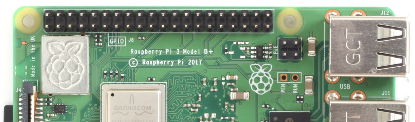
You can find the so-called “pinout”, which documents the roles of these pins both in the BCM2835 datasheet and, more conveniently, on the internet.
We will only use three pins:
- One pin, pin 8, configured to serve as a transmission (“TX”) pin for the UART.
- One pin, pin 10, configured to serve as the receive (“RX”) pin for the UART.
- A ground pin (e.g., pin 6) to connect the UART line to the same ground as the Pi itself.
Important Note: The Raspberry Pi has two ways of counting pins:
- Physical pins, which run from 2 (left top) to 40 (right top) and 1 (left bottom) to 39 (right bottom).
- “GPIO” pins, which are arranged fairly arbitrarily on the board (e.g., “GPIO 17” is next to “GPIO 27” on physical pins 11 and 13).
The BCM2835 datasheet (e.g., the table on page 102) uses “GPIO” pin numbers, and so must our code. The easiest way to deal with this is to use sites like pinout.xyz to translate the numbers.
Since there is a limited number of pins, the hardware allows reconfiguring them for different functionalities by programming special device registers for GPIO control. Hence, we must first assign the UART functionality to the relevant GPIO pins and enable them.
A note on emulation vs. real hardware: QEMU actually doesn’t emulate the GPIO pin configuration, so your code will work in QEMU even if you skip this step. However, it won’t work on the real hardware—a classic mismatch between emulation fidelity and the complexity of real hardware. One of the pains of OS development is navigating these mismatches, and this is a good example of one. If you are in CS 1690/2670, you will need to test your GPIO pin configuration code on real hardware to make sure it works (see below).
The GPIO configuration code is somewhat arcane, and we give it to you rather than having you write it (although you are welcome to work it out yourself if you want to).
Task: Part 1: First, use the BCM2835 manual to determine the offsets of the GPIO device registers (GPFSEL0, GPFSEL1, GPPUD, and GPPUDCLK0) that you will need to configure the GPIO pins for the UART. Put these offsets in kernel/drivers/gpio.h instead of our placeholder values of 0x0.
Part 2: Then, write a function gpio_init(), either in kernel/drivers/uart.c or in a new file (e.g., kernel/drivers/gpio.c). This function should configure and enable the necessary GPIO pins for the PL011 UART device.
Just give me the code...
Here’s the code you need for gpio_init(), based on the “Synopsis” text on page 101 of the BCM2835 datasheet, under the “GPIO Pull-up/down Clock Registers (GPPUDCLKn)” heading.
void gpio_init() {
  // Select the right alternative function for each pin we're using
  unsigned int selector = mmio_read32(GPFSEL1);
  selector &= ~(0b111 << 12);  // clear bits for pin 14
  selector |= 0b100 << 12;     // set pin 14 to ALT0 functionality (TXD0)
  selector &= ~(0b111 << 15);  // clear bits for pin 15
  selector |= 0b100 << 15;     // set pin 15 to ALT0 functionality (RXD0)
  selector &= ~(0b111 << 18);  // clear bits for pin 16
  selector |= 0b111 << 18;     // set pin 16 to ALT3 functionality (CTS0)
  mmio_write32(GPFSEL1, selector);

  // Enable the GPIO pins
  mmio_write32(GPPUD, 0);      // disable pull-up/down for pins 14, 15, and 16
  delay_cycles(150);
  // enable clock for pins 14, 15, and 16; a clock signal is necessary so that
  // the configuration change actually gets applied
  mmio_write32(GPPUDCLK0, (0b1 << 14) | (0b1 << 15) | (0b1 << 16));
  delay_cycles(150);
  mmio_write32(GPPUDCLK0, 0);  // disable clock again
}
This code uses the delay_cycles function from kernel/utils.{h,c} to make the CPU wait for some time, so you will need to #include the appropriate header file.
I want to write it myself!
This task is most easily completed by:
- carefully reading the description of the “GPIO Function Select Registers (GPFSELn)” on page 91 of the BCM2835 datasheet,
- looking at the Alternative Function Assignments table on page 102; and
- carefully reading the “Synopsis” text under the “GPIO Pull-up/down Clock Registers (GPPUDCLKn)” heading on page 101. This text gives you the algorithm you need to follow, although you will still need to figure out which GPIO device registers to use.
Note that you need to configure pins 14, 15, and 16, but not the ground pin (e.g., pin 6), since the ground pin doesn’t send any data.
Hints
You will need to make the CPU “wait” for some number of cycles in order to implement this. But you don’t have a timer yet, so you’ll need to do this by wasting instruction cycles. Think about how you might achieve this, or read and use the delay_cycles function in kernel/utils.{h,c}.
🤖 AI use/coding: allowed, including agentic coding, except for finding the register offsets in the manual (part 1). Since we give you the code for part 2, you can of course alternatively use AI to generate it.
Why? We want you to become familiar with looking up device registers in the hardware manual, so we ask that you do this part yourself. The code for GPIO pin configuration is necessary, but the details of it—including the algorithm to enable GPIO pins—are very specific to the Raspberry Pi’s hardware. While going through the process of translating an “algorithm” outlined in a hardware manual into actual code is educational, we decided that this isn’t the best place for you to spend lots of time (unless you want to). You’ll write the next piece, the actual UART driver, by hand.
For context, see the principles around AI use in CS 1670.
Now, in the next step, you can write the actual UART driver.
Some useful advice for writing device driver code, including the GPIO and UART driver code:
- Treat a device register as
volatile. Wrap the raw addresses in helpers that read/write avolatile uint32 *, such as themmio_write32andmmio_read32macros that we provide inkernel/utils.h, so the compiler never reorders assembly instructions that access this memory and ensures the “data” in those addresses doesn’t get stored in CPU caches. A device register is not ordinary memory. - Most device registers are bitfields, meaning that you need to set individual bits or sequences of bits in them. You can do this in numerous ways, but we find that the easiest is to write your desired bit sequence as a binary constant (e.g.,
0b110for 1102 = 610) and then shift it left to the right bit position (e.g.,(0b110 << 7)to change bits 7, 8, and 9). To set multiple fields, you can binary OR them together: e.g.,(0b110 << 7) | (0b1 << 3)sets bits 7-9 to110and bit 3 to1. - Always read and write device registers in their entirety (e.g., 32 bits for the UART registers). When using your helpers,
mmio_write32andmmio_read32, the compiler will generate the correct assembly for this.
Some UART-specific notes:
- You’ll need to configure the correct speed (a “baud rate” or data rate) for the UART. This is done by writing values to two registers that represent the integer and fractional parts of a divisor (a value that the hardware needs to divide another value by in order to produce the right baud rate). The dropdown below explains how to do this.
Computing the baud rate
You must configure the UART for a standard rate (e.g., 115,200 baud, 8N1: 8 data bits, no parity, 1 stop bit). The manual gives a formula relating the baud-rate divisor to the UART’s input clock, and the divisor has an integer part and a 6-bit fractional part, programmed into two separate registers.
Unfortunately, the clock frequency (FUARTCLK) isn’t obvious in the manual. For the PL011 UART, it is 48 MHz, so the formula becomes:
baud_divisor = 48,000,000 / (16 * baud_rate)where baud_rate is your target baud rate (e.g., 115,200). However, the divisor often has a fractional component, so can’t be represented as a single integer. This is why the hardware provides two registers: one for the integer part (IBRD) and one for the fractional part (FBRD). The formula for computing the divisor from the two parts is:
baud_divisor = IBRD + FBRD/64If you work through this math, you’ll find that for 115,200 baud, the divisors are 26 for the integer part and 3 for the fractional part. (Getting the fractional part wrong typically produces garbage characters rather than silence.)
- The manual’s synopsis of the
CRregister (page 185) notes a programming sequence for the control register (disable, then configure, then re-enable). Don’t skip the disable step: the hardware reacts funnily to being reconfigured while it’s operational. - You’ll want to enable Clear-To-Send (CTS) flow control, which is a hardware feature that prevents the UART from sending data when the receiving device isn’t ready. This is done by setting a bit in the control register. While this doesn’t matter in QEMU (its hardware is always ready), it will matter if you connect your Raspberry Pi to a real (and slow) UART device.
- Develop your UART code in stages and test after each. First get a single known character out of
uart_send(e.g. send'!'in a loop directly in the driver function). Only once one character works should you build up sending whole strings. - If you see nothing at all: re-check the GPIO alternate-function setup and the peripheral base.
- If you see garbled characters: re-check the baud-rate divisor.
Task: Write a device driver in uart.c, with its public interface as function declarations in uart.h. Your device driver should provide at least the following public functions:
uart_init()— configures the RPi’s GPIO pins for the UART, then sets up the UART device itself: disables it, sets the baud rate, sets 8-bit word length and enables the FIFO, and finally enables the UART with transmit, receive, and Clear-To-Send (CTS) flow control. The order of these operations matters and the manual/datasheet spells it out; make sure to follow it. One ordering constraint that the manual isn’t explicit about is that you must configure the baud rate before you configure the line control register (LCRH).uart_send(char c)— polls the flag register until the transmit FIFO has space to output more data, then write the byte to the data register. We are developing a polling driver: if there is no room, your code should busy-wait in a loop. We are deliberately not using interrupts yet.uart_send_string(const char* s)— sends a C string. You can implement this via repeated invocation ofuart_send.
🤖 AI use/coding: auxiliary use allowed. You are welcome to use AI to draft pieces of code for your driver, and to help with bit-level manipulation of registers. However, you are not allowed to task a coding agent with writing the entire device driver for you. The driver is quite short (our reference implementation has 71 lines), so we recommend that you just write the code entirely yourself.
Why? Bit-level manipulation, shifting, and using hexadecimal constants is common in driver code and one of the learning goals of this assignment is to expose you to this style of programming. But it can be confusing when you’re new to it; having AI help you get this right and learning from it is reasonable and helps you be productive. However, we want you to actually see what’s involved in building a device driver. This is because drivers make up a large fraction of OS code and because you’ll be better able to debug AI-generated driver code once you know how it fits together.
Important note: even though you can use AI here, you must understand every line of your code because you’ll work with the code in the future. We will ask you to edit and explain your device driver in a whiteboard discussion.
For context, see the principles around AI use in CS 1670.
Helpful hints for effective AI use
AI is extremely good at explaining some of the confusing underlying hardware concepts at play here. For example, we found that AI explained the baud rate calculation much better than the manual did, and we’d encourage you to leverage it to help you with that.
Be sure to mention to the AI that you’re working with a “PL011” (P-L-zero-eleven) UART, rather than a “UART on the Raspberry Pi” or “UART on the BCM2835,” since the latter two are ambiguous and will lead to confusion. The Raspberry Pi has multiple UART chips, and some of them work differently from the one we’re using here. We target the PL011 UART design because it is used in many ARM-based systems, including the Raspberry Pi.
Part C: write printf
Now that you can output characters via the UART hardware, you’ll want a familiar abstraction for writing strings, numbers, and formatted text. The UART just expects ASCII characters, so to print a number (such as your value of π), some code must run that converts integers into ASCII characters. Likewise, turning a format string such as "%x" into a hexadecimal integer like 0x123abc requires code that implements this translation. On a normal system, the C standard library provides this functionality, and exposes it to your code via the printf function. But our computer so far has no C standard library or OS, so we must write it ourselves.
If you read the man page for printf, you’ll find that it supports a very complex set of format syntaxes. You won’t need all of them—for example, there is no need to print floating point numbers—but you’ll want to at least support printing numbers, strings, and pointers (i.e., hexadecimal numbers).
The basic logic behind printf is to iterate through the format string with a state machine consisting of two states:
- When the iteration encounters a
%, it enters the “inside format specifier” state, trying to parse a format specifier like%d. Once that succeeds, the function emits the data passed in the nth argument (converting it as necessary) for the nth format specifier and returns to the “normal character” state. - Otherwise, in “normal character” state, the iteration just emits the character.
“Emitting” a character means actually sending it to the output: in your case, this means calling uart_send. Your implementation should also handle error cases correctly—a printf that doesn’t do so can easily corrupt memory and is naturally hard to debug.
Task: Build a printf-style function on top of uart_send. Usually, this is done by writing both a variable-argument printf wrapper and a vprintf function that takes an argument list and implements the actual logic. Both should go in kernel/printf.c, and you’ll want to expose both printf and vprintf via kernel/printf.h. Your implementation should, at minimum, support and correctly handle the following format specifiers:
%d/%u(integers),%ld/%lu(long integers),%x/%lx(hexadecimal integers) with leading zero-padding,%p(a hexadecimal pointer value),%c(a single character),%s(string), and%%(literal%).
🤖 AI use/coding: allowed, including agentic coding. You can generate your printf function with AI or use an agent to implement this task. See below for some important and helpful hints on how to do so effectively. If you wish to write printf yourself, we certainly encourage you to do so—it is not very long (79 lines in our reference implementation). In this case, you’ll want to look at types.h, which contains some declarations for variadic functions like printf.
Why? Implementing variadic functions and integer-to-string conversion from scratch in C is fiddly. While it’s interesting for your general education and we encourage giving it a go, the learning goals for this course and assignment aren’t about how to implement variadic functions in C or about the details of printf. However, you must of course understand the code and how it works.
For context, see the principles around AI use in CS 1670.
Helpful hints for effective AI use
When prompted to write a printf function, AI in our experience is prone to make assumptions about the environment (e.g., running in userspace atop standard syscalls) and to going for the easiest solution. Make sure that your prompt includes the following information:
- Mention that this
printffunction is for a “baremetal” or “freestanding” environment (or to be used inside a kernel), and no standard library is available. - Explain that
uart_sendis the function to call to emit characters. - Explicitly restrict the supported format specifiers (otherwise the AI will generate, e.g., floating point support that won’t work).
- Emphasize that errors in format specifiers or input arguments must be handled, e.g., by calling
uart_send_stringwith an appropriate error message.
If you want to test your printf implementation, you can modify kernel/pi.c to print various values in the pi_main function.
Note on line endings. A serial console generally wants a carriage return and a line feed (
"\r\n"), not just"\n", to start a new line cleanly. This is because early output devices like typewriters differentiated between “carriage return” (which moved the print head to the beginning of the current line) and “new line” (which moves the print head down, but not back to the start of the line).
Part D — print π
Now it’s time to use your printf to produce the output from the computation your program is doing.
Task: Change kernel/pi.c and set the PI_PRINT constant to 1. This will cause the program to print the estimate to the console.
🤖 AI use/coding: not allowed. It’s a one line change 😃
Check your work
make qemu and watch your terminal. You should see your π estimate printed, e.g.:
pi ~= 3.1415926535...(However you choose to format it.) Test printf with a few format specifiers and values to be confident it’s correct, as you’ll depend on it in Task 3.
Bonus Quests (Extra Credit)
CS 1670 projects will, on occasion, offer ✨ super fun extra credit quests ✨. These give you a chance to engage more deeply with the material and also have some fun.
Important note: All extra credit work will require you to meet with an instructor at office hours to discuss your work in order to get credit. There will be no exceptions to this, since extra credit is strictly optional.
Quest 2-E1: Control Characters and Escape Codes (moderate difficulty)
Printing ASCII characters is the most common operation and, at least since ~1961, supported by most output devices. But output devices such as teletypes and printers also support so-called “control characters”. These do things like, e.g., moving the print head, changing the font, or adding underline or bold (overprint) formatting. Control characters were originally not standardized at all: each device specified its own set in the manual, and device-specific drivers had to implement them.
Control characters are also sometimes referred to as “escape codes”, since many of them are multi-byte sequences that start with ASCII character 0x1B (decimal 27), which the standard labels ESC (and which is what your keyboard sends when you press the “ESC” key). For example, 0x1B 0x1F turns on bold printing on Malte’s daisy wheel printer (the Tandy DMP-230), while 0x1B 0x5B 0x35 0x77 changes the font on the DECwriter Correspondent (a Teletype-like terminal device) to a wide-character font.
Task (extra credit): Research the control characters for the Tandy DMP-105 (dot matrix printer), the Tandy DWP-230 (daisy wheel printer), or the DECwriter Correspondent and implement support for some of them in your printf function. You may want to start your research by finding a manual for the device you’re targeting. While long out of print, some kind people on the internet have scanned physical manuals to preserve them. Two helpful hints:
- There is no manual online for the DWP-230, but there is one for the (very similar) DWP-220.
- For the DECwriter, you want the “Programmer Reference Manual” rather than the “Operators Manual”.
We’d recommend focusing on control characters for “pitch” (horizontal: character spacing/size; vertical: line spacing) or formatting options, such as underline or bold, since these will produce the most fun output.
Note that you won’t be able to test this functionality in emulation: you’ll need the real hardware to see if it works. You can either implement this blindly and hope it works, or come to instructor office hours to test your implementation with a real device.
🤖 AI use/coding: allowed, including agentic coding. We generally allow you to use AI for extra credit quests, but you must understand your implementation fully. To get credit for solving the extra credit quest, you will need to discuss your work with an instructor in person.
Quest 3: An OS that runs programs in sequence
Files: kernel/kernel.c, kernel/elf.c, kernel/init.c, and headers and user programs in user/.
You may be concerned about how close the project deadline lecture 3 happens. Fear not: this part only requires you to write six simple lines of code, so you’ll easily be able to complete it within the 1.5 days after the lecture.
Overview
So far you have one program welded to your boot code: in other words, depending on your viewpoint, the program is either part of the “OS” or your computer has no OS and needs to restart in between different programs. A real OS runs many programs and they are ordinary executables that exist independently of the kernel. In this final task, you will build a small OS kernel that:
- Loads several executables into memory in turn. Loading turns a compact executable file into a running program laid out in RAM (this requires you to add a loader to your OS).
- Runs several programs in sequence. This is “batch processing”, a computing paradigm loads a program, runs it to completion, load the next, and so on.
- Shares services with user programs. You will make your kernel’s
printffunction (and thus the UART driver underneath it) available to every program through a shared library,user/u_klib.h, so the programs don’t need to each re-implement the function or be compiled with the operating system.
Why are we doing this?
This is where the two roles of an OS—abstraction and mediation—become concrete. The program loader and the shared printf are abstraction: a program executable contains its machine code plus a description of how to lay it out in memory, but the loader decides on the actual memory locations for its segments. The program also gets I/O “for free” without knowing about UARTs by calling into the printf library function. The loop running programs one after another is mediation: the OS, not the programs, decides who runs and when.
In this part of the assignment, you also see the central distinction between an executable (a file) and a process (that file brought to life in memory), and see how the OS chooses where in memory to put a process.
Background: executables vs. processes, and the ELF format
The user programs in user/ are compiled and linked into ELF files. ELF stands for the Executable and Linkable Format, the same format Linux uses. An ELF file is not a memory image you can jump into directly. It is a structured file:
- An ELF header at the very start identifies the file (a “magic number”,
0x7F 'E' 'L' 'F'), the architecture (you’ll check for AArch64), the entry point (the address of the first instruction to run), and where to find the program header table. - A program header table describes segments. Each segment says: take these bytes from this offset in the file, and place them at this virtual address in memory, occupying this much space. The segments that must be loaded into memory are marked
PT_LOAD.
So “loading a program” means: parse the header, walk the program headers, and copy each loadable segment from the file into memory at the right place; then, finally, jump to the entry point. The file representation (compact, on “disk”) and the running representation (segments spread across memory) are different ways of laying out the same initial data, and the loader is what bridges them.
Where do programs go in memory? You might wonder who decides where each program goes when loaded. The answer is that the kernel decides. Your kernel reserves a region of physical RAM for user programs and places each program’s segments there. Because there is no virtual memory or memory protection in this project, the address the kernel loads a program at is a real physical address, and the kernel must make sure programs don’t collide.
What you need to do: loading programs
We’ll tackle this problem in three steps, each of which require very little code.
- Boot into an actual kernel. You’ll change your bootup code to call into a shared OS kernel, rather than into
pi_main. - Have the kernel load a program. You’ll add an ELF loader to your code base and write kernel code that calls into the ELF loader to load an executable.
- Run a batch of programs. Once you have one program working, simply load and execute the next one after it completes.
Task: Give a name to your OS! You can be as creative as you like. You’ll need the name in the next step.
🤖 AI use/coding: allowed. Why? Naming is a creative task and you’re welcome to use AI to help you brainstorm ideas, or to do the creative part yourself. You may also design or use AI to generate a logo for your OS (you’ll use this later), but this is optional at this point.
Now, let’s write some code.
Task: Write a kernel_main function and jump into it from your bootup code. We suggest putting this function in kernel/kernel.c. The function should:
- Initialize the UART (so you can print output).
- Print a message to the console (e.g.,
"Hello world from <YOUR OS'S NAME>!\r\n"). - For testing purposes, call
pi_main()to compute π and print it. (This checks that the new code added didn’t break any existing functionality.)
At this point, you should have the same functionality as before. You can test this by running make qemu and checking that you see the “Hello world” message and the computed value of π.
🤖 AI use/coding: auxiliary use allowed. Why? We would like you to know how your kernel takes control of the hardware by comprehending how execution flows from bootup assembly to programs.
For context, see the principles around AI use in CS 1670.
Now, we are ready to add an ELF loader and load programs that exist on storage. In our case, the “storage” will be somewhat fake, since we don’t have an SD card driver or file system yet. Instead, your kernel image (the kernel’s ELF file) will be holding the executable file’s bytes in memory, and so that the Raspberry Pi’s bootup sequence loads them into memory alongside the kernel. The program loader will then read the bytes of the executable from memory, copy them into the right place in RAM, and then jump to the program’s entry point.
Writing a program loader is a fun and educational exercise that really makes you understand the ELF executable format, but is also fiddly and time-consuming. We therefore provide you with a pre-made loader in this repository. While you’re welcome to write your own (with or without AI), we’d suggest copying over the provided loader code.
Task: Add an ELF loader to your codebase, either by copying the provided one or by writing your own.
If you are using our provided ELF loader...
Look at this repository.
- Struct definitions for the ELF header and program headers are in
elf.hand you should copy them tokernel/elf.h. - The actual loader, implementing in
load_elfand helpers, is inelf.cand you should copy it intokernel/elf.c. - Our loader assumes that a function
panicexists that prints an error message. You can write such a helper by simply wrappingprintf(use AI to help you with the variable argument syntax), or replacepanicwithprintfin the loader code. A dedicatedpanicfunction is useful for debugging, since it can print a message and then run an infinite loop to halt the CPU.
If you want to write your own ELF loader...
Inside kernel/elf.c and kernel/elf.h, write the code for a function that takes (1) a pointer to an ELF image in memory, and (2) a physical memory location to load the image at. This function should do the following:
- Validate the ELF header: check the magic number, that it’s a 64-bit little-endian AArch64 executable. If something is wrong, panic with a clear message.
- For this purpose, you may wish to implement a
panichelper inutils.{h,c}by wrappingprintf(use AI to help you with the variable argument syntax), you can useprintf. A dedicatedpanicfunction is useful for debugging, since it can print a message and then run an infinite loop to halt the CPU. - Walk the program headers; for each
PT_LOADsegment, copy its bytes from the image to the program’s destination in memory. - Compute the entry point’s actual address in memory and return it from
load_elf.
Hints:
- Build the loader incrementally. First just validate the header and
panicon a deliberately corrupted file. Then load segments butpanic/print instead of jumping. Only when the layout looks right should you jump to the entry point. - A printing routine that dumps the ELF header and each program header (magic, class, entry point, segment offsets/sizes) is enormously helpful for debugging, and a good early thing to write. Compare its output against
aarch64-elf-readelf -a user/<prog>.elf(macOS native) oraarch64-linux-gnu-readelf -a user/<prog>.elf(container) on your host. - Be careful with addresses: the entry point in the ELF header is relative to where the program thinks it’s loaded; the actual call target is that plus the base address where you placed the segments. Off-by-one-region bugs here are common, so make sure to print the addresses.
We will test the ELF loader in the next step.
🤖 AI use/coding: allowed, including agentic coding. You can generate your ELF loader with AI if you want.
Why? The details of the ELF format are interesting, but beyond the scope of this course. We will not ask you to explain details of the ELF loader.
We will now change kernel_main to call into a function called init. The init function should invoke the ELF loader to load a program. For example, a typical init function might look like this:
void init(void) {
    // Load the first program
    void* entry_adr = load_elf((void *)executable_address_in_memory, (void*)start_of_process_memory);
}
Where’s the executable? You might wonder where executable_address_in_memory comes from. The answer is that we configured the linker to place each ELF executable from the user directory into a known location in the kernel’s memory image. The linker helpfully adds a label for each such executable, which you can reference in your code. For example, if you have a user program called user/hello.elf, the linker will add a label called _binary_user_hello_elf_start that points to the start of that program’s bytes in memory. We include extern declarations for these labels in kernel/init.c, so you can reference them in your init function.
Where should the program go in memory? The second argument to load_elf, the pointer start_of_process_memory, is a memory address that will serve as the start of your process’s memory region. The program loader will put your program’s segments starting at that address. You can pick any address you like, but it must not overlap with other memory regions you have already defined (e.g., the kernel memory and the initial kernel stack). A good way of going about this is to define a constant in kernel/memlayout.h that marks the start of the user program memory region (e.g., PROC_START) and another constant that defines the amount of memory to reserve for each process (e.g., PROC_SIZE). Then, in your init function, you can load the first program at PROC_START, the second at PROC_START + PROC_SIZE, the third at PROC_START + 2 * PROC_SIZE, and so on.
You might wonder what good values to pick for these are. A good starting point is to pick PROC_START to be a few megabytes above the kernel’s memory region, and PROC_SIZE to be relatively small, like 16 KiB (0x4000). For example, if your kernel starts at 0x8'0000 and you give it up to 1 MiB of memory (0x100000 bytes), you might pick 0x18'0000 as your PROC_START and reserve 16 slots for of PROC_SIZE at that address. You may need to adjust these values in the future; eventually, adding support for virtual memory to your OS will take care of no longer having to set them carefully.
Task: Now update your memory layout diagram to reflect the memory region you have set aside for user programs.
🤖 AI use/coding: NOT allowed. Why? We want you to maintain a mental image of your memory layout.
For context, see the principles around AI use in CS 1670.
What you need to do: library functions & running a program
Background: how user programs reach printf
We would like to provide a single printf implementation that all programs can share, rather than each program having to implement format string parsing, character emitting, and calling uart_send itself. (In fact, one reason this is important is because it avoids programs making assumptions about what UART device they’ll be using: in our case, the UART is a PL011, but in a different system it might be a different device with a different interface.)
Each user program is compiled separately from the kernel, into its own ELF file. It therefore cannot link against the printf in our OS kernel code: at the time the user program is compiled, your kernel executable doesn’t exist yet and the address printf will have in it is unknown.
The classic solution is an agreed-upon address. The kernel makes its printf reachable at a fixed, known location in memory; the user side hard-codes that same location and calls through it. You will set this up in user/u_klib.h: this file declares how a user program obtains and calls the kernel’s printf function, using an address you hard-code to match where your kernel actually places it. This is a stripped-down version of the same problem real systems solve with system calls and a stable ABI—here, with no protection boundary in the way, a shared function pointer at a known address is enough.
In addition to loading the program, we need to make the library function vprintf available to it. The solution—as alluded to above—we’re going with here is to put the memory address for the function’s machine code into a known location. If you look at kernel/memlayout.h, you’ll see a constant F_BASE that defines a memory address (currently a placeholder of 0x0), and a constant F_VPRINTF that indexes into eight bytes below that address (e.g., if F_BASE was 0x1000000, then 0x0FFFFF8 corresponds to F_VPRINTF). Your kernel_main function should write the address of your vprintf function in the code segment into that location, so that user programs can call it. The code that lets user programs actually call printf to invoke the kernel’s vprintf via this mechanism is already in user/lib/u_common.c in case you’re curious.
To actually run your loaded program, you’ll need to do some C shenanigans, which we suggest placing into an exec helper function. In essence, you should cast the loaded program’s entry point to a function pointer and call it. For example, if entry_adr is the entry point of the loaded program, you can run it with:
void (*program_entry)(void) = (void (*)(void))entry_adr;
program_entry();
Task: First, change F_BASE in kernel/memlayout.h to an address that is at least a few thousand bytes away from any address you’re already using in your memory layout, and update your memory layout diagram to reflect the region of memory used for the library function pointers. Then, change kernel_main to store the address of vprintf in the predefined location F_VPRINTF. Finally, write an init function that loads and runs a program.
We suggest the following to help you do this:
- Creating a helper for saving the library addresses.
- Placing the
initfunction intoinit.cand either adding anexterndeclaration to the file that has yourkernel_mainfunction or to add ainit.hheader file that you#includefrom the file with yourkernel_mainfunction.
To test your work, load and run the user/squares.elf program, which prints a list of squares to the console. You should see the list printed after your kernel’s “Hello world” message.
Hints
- The syntax for storing the address of
vprintfinto the memory locationF_VPRINTFis a bit gnarly. In particular, the left-hand side of the assignment is a pointer to a pointer to a function (cast to*(void (**)(arg1_type, arg2_type)), wherearg1_typeandarg2_typeare the types for the first and second argument to the function, respectively, if any). The right-hand side is the address of a function. You can use AI to help you get this right.
🤖 AI use/coding: auxiliary use allowed. You can use AI to understand what you need to do and debug function pointer code.
Why? Function pointers are a particularly unintuitive part of the C language, and using AI to get them right is a good use of the technology. However, we want you to understand what hactually happens in your OS when it runs a program, so you must write the actual code and fully understand it.
Finally, let’s run a “batch” of programs! You’re nearly there.
Task: Change your init function to load and run the following programs in sequence:
user/squares.elf(prints a list of squares);user/pi.elf(computes and prints π);user/primecheck.elf(finds prime numbers forever).
After the last program runs, your OS will be done. You can either halt the CPU (research how to do this) or enter an infinite loop in kernel_main; in practice, you won’t get there with these programs because primecheck runs forever.
Hints
- You can use the same memory region for all three programs, since they run one after another; basically, load each program at the same address (e.g.,
PROC_START). This will no longer work in the next project, however.
🤖 AI use/coding: auxiliary use allowed. You can use AI to understand what you need to do and plan your code.
Why? This is a three-line change, so AI use is unlikely to be necessary or helpful, but we allow it because you might encounter hard-to-debug errors.
Check your work
If everything works, make qemu should boot your newly-minted, still very basic kernel and then run your programs one after another, printing the “hello world” message and any output the programs themselves produce (including, via u_klib.h, output from a program that calls your shared printf). For example:
Hello world from <YOUR_OS'S_NAME>!                              # output from your kernel
1   1   0                                                       # output from user/squares.elf
2   4   3
...
pi ~= 3.1415926535...                                           # output from user/pi.elf
...
primecheck: Found another 1000 primes; last one was 7919!       # output from user/primecheck.elf
...
And with that, you are done, except for one last task!
Task: As your final step, review your memory layout diagram, put a copy of it into docs/memlayout-physical.pdf, and push it to GitHub.
🤖 AI use/coding: NOT allowed.
Why? As always, we want you to understand your OS’s memory layout.
Congratulations, you have created your own OS that boots and runs multiple programs in sequence! You have completed the project 🎉.
Bonus Quests (Extra Credit)
Quest 3-E: Loading Programs over the UART (high difficulty)
Early computers would load programs via punched cards or paper tape. But operating these devices required a device driver, so it was common for human operators to manually “key in” a loader program via physical switches on the front panel of the computer. The loader would then read a program from punched cards or paper tape and load it into memory. Your ELF loader is a more modern version of this idea, but fortunately doesn’t need to be entered manually because the Raspberry Pi has firmware that loads the initial kernel image from the SD card.
But you can also implement a loader that reads a program over the UART console, much like early computers would have read paper tape. The idea is that when starting up, your kernel jumps into a loader that expects to read ELF files from the UART console. The loader reads the bytes of the ELF file, loads it into memory, and then jumps to its entry point.
Task (extra credit): Implement a loader that reads ELF programs over UART. You’ll need to add support for reading bytes from the UART console, and then implement a loader that reads an ELF file over the UART, invokes your ELF loader to load it into memory, and then jumps to the program’s entry point. When implementing UART reads, you should implement a polling read, not an interrupt-driven one, at this point.
To test your loader, you will need to send an ELF file to the QEMU UART console. This is a bit fiddly, but you can do it by asking QEMU to expose the serial console as a named pipe or TCP port and then send data via cat or netcat. You can also use a real Raspberry Pi and send the ELF file over a serial console connection from your computer.
🤖 AI use/coding: allowed, including agentic coding. We generally allow you to use AI for extra credit quests, but you must understand your implementation fully. To get credit for solving the extra credit quest, you will need to discuss your work with an instructor in person.
Handing in & grading
You will submit your work via git, using our grading server.
Before you submit, make sure that:
make clean && make qemubuilds and runs without errors from a fresh checkout.- Your code is formatted (
make format) and free of debugging spew you didn’t intend to leave in.
Submitting your code (and checking on the grading server)
Your submission will not be graded until you configure the grading server. You should have used the grading server for Project 0 already.
If you were registered for CS 1670/1690 on the first day of classes, you should have received credentials by email.
If you only recently registered or you’re shopping the course but haven’t registered, you won’t have an account yet. In that case, please complete this form and wait until you receive your credentials. We will create accounts based on the form entries at 8pm every day.
To submit your work, please do the following:
- Log into the grading server with the password you received. Once you’re logged in, enter your GitHub username (at the top).
- Connect your repository by adding the repository URL under the “Project 1: Booting” category. Click “Project 1: Booting” to initiate a fetch of your repository from GitHub.
- Note: If your GitHub account is not linked to your Brown email address, the grading server will give you a command to run to verify your project repository.
- Check your code works: On the “Project 1: Booting” page, use the buttons below the commit list to test your code in our grading environment. Make sure it still works as expected!
- Set your grading commit: finally, press the “Grade this commit” button to tell us which commit you want us to grade. Some notes about this:
- You can reassign your grading commit at any time before the 72 late hour cutoff. If your commit is after the deadline, the grading server will tell you how many late hours it uses after selecting it from the dropdown.
- Click the “Run submission checks” button to run a set of tests that tell you if there are any known problems with your handin. Passing this check doesn’t guarantee that everything works or is correct, but catches some common issues early.
- After submitting your work, please sign up for a Whiteboard discussion.
Extra requirements for CS 1690/2670 students
In addition to submitting the project, you must also check that your code works on the real hardware. For this, you should do the following:
- Ensure that your UART configuration is correct, since real hardware is less forgiving on mistakes in this code than QEMU is. You can use the “UART settings test [1690/2670 only]” button on the grading server to check that your UART configuration is correct.
- Run your code on a real Raspberry Pi. We won’t give you hardware until enrollment has stabilized by the end of shopping period, but in the meantime you can can run on real hardware remotely using the “Run on hardware [1690/2670 only]” button on the grading server, or by coming to instructor office hours to access a real Raspberry Pi. You can find the times of Malte’s and Nick’s office hours on the course calendar.
Note that we only have a single remote-accessible Raspberry Pi and that resetting it for another student to run their code takes about a minute. Don’t leave this to the last minute, as there may be high demand on the remote hardware close to the deadline and you may not be able to test your code in time.
Congratulations, you’ve completed the first project! 👏
Grading breakdown
Your grade comes in two parts:
- Functionality: We will run your code on the grading server and check that it works as expected (i.e., runs the three programs in turn). This is worth 50% of your grade and impacts the “Projects” part of the course grade.
- Whiteboard Discussion: You will meet with a course staff member in a small group to discuss the concepts in this project for 45 minutes. The discussion is worth 50% of your grade and impacts the “Whiteboard Discussions” part of the course grade.
We will grade both components according to our honest grading scale.
Footnotes
The Raspberry Pi is based on a processor made by Broadcom called the VideoCore, which was originally intended as a graphics processor (GPU) for mobile devices. The VideoCore chip also includes an ARM64 processor, but the ARM processor is a secondary component (even though it is the main component we’ll be using for this course). This design is called a “system on chip” (SoC), which combines multiple processor elements on a single physical chip. Interestingly enough, some modern AMD x86-64 processors use a small ARM64 processor to start up the x86-64 processor. ↩︎
If you think this through, you’ll notice that this is a rather wasteful encoding: to represent 0 through 9 in binary, we only need four bits, but we use a full 8-bit byte. This is a concession to the fact that we use a modern computer, as some early-day computers used fewer than 8 bits per byte or digit. Indeed, Brown’s first computer, the IBM 7070, used five bits to represent every digit, based on a rather strange encoding. ↩︎
MMIO has the somewhat funky property that even reading a device register can cause things to happen in hardware! In other words, MMIO reads can have side effects. We won’t see this with the UART device, but it is relevant for more advanced devices. ↩︎